Simple framework for keeping gear honest
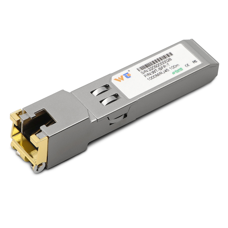
I work with factory crews and field techs, and I lay out a plain five-step framework that keeps an optical transceiver from leaving the shop half-baked. Start to finish, the shop should run functional checks, optical inspection, environmental stress, link integrity and final packing verification. If you buy parts from an optical transceiver manufacturer, expect each stage to be logged and traceable. These checks cover SFP module basics like wavelength, insertion loss and basic BER so the kit doesn’t surprise you in a live rack.
Stage 1 — Functional smoke test
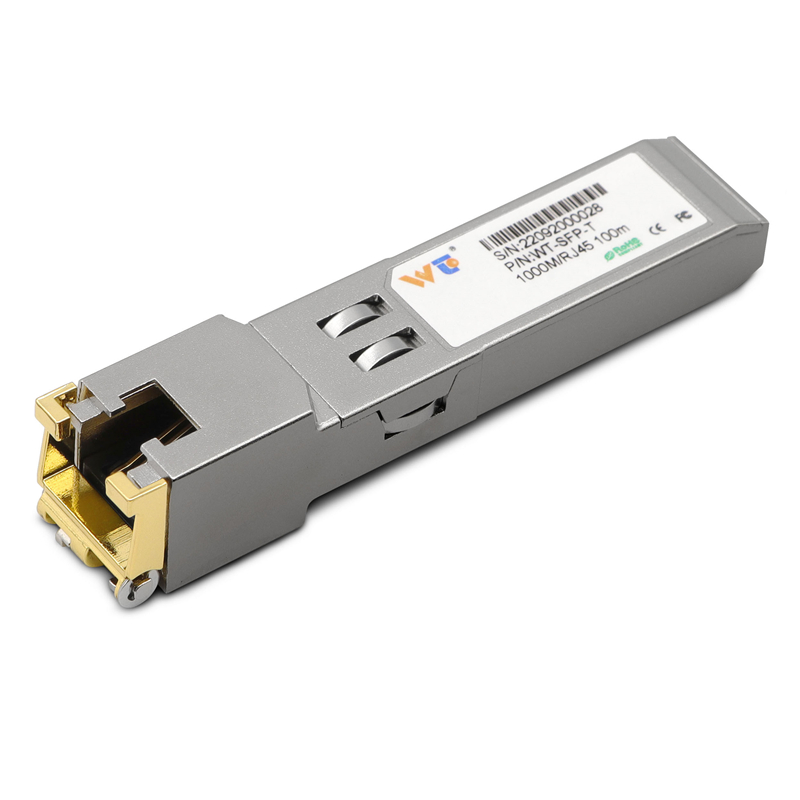
First thing: power and baseline comms. Technicians confirm the module initializes, the laser fires within spec and the digital diagnostic monitoring (DDM) returns sane readings. This stage catches outright failures fast; a dead SFP or mismatched transmitter/receiver pair fails here. Keep firmware and boot diagnostics in the record so modules trace back to batch numbers if a fault pops up later.
Stage 2 — Optical alignment and connector inspection
Clean ferrules, check end-face polish, measure insertion loss and reflectance. Use microscope inspection plus a calibrated power meter to log loss at both wavelengths relevant to the transceiver. Bad or dirty connectors cause intermittent errors in real networks — catch those with visual and power tests before anything moves to thermal stress.
Stage 3 — Environmental and thermal cycling
Put parts through thermal cycles that match shipping and field conditions: repeated runs between the stated lower and upper operating temperatures for the product (for example, -40°C to +85°C for industrial grade) with dwell times to let optics stabilize. Log DDM over the cycle to spot drift. This stage reveals solder joints, connector seating problems and wavelength drift under real stress.
Stage 4 — Link integrity and BER validation
Run a sustained data test across a representative fiber run to measure bit error rate (BER) and jitter under load. Use line-rate traffic and stress patterns, then evaluate packet loss and error counts over a set window — for many deployments, acceptable BER is 10^-12 or better over the test period. Record results and compare to acceptance thresholds so the factory output is network-ready.
Stage 5 — Final configuration, labeling and packing
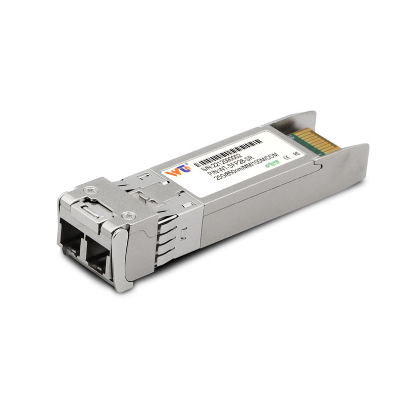
Confirm the transceiver reports correct vendor, part number, wavelength and serial in its SFP DOM registers. Attach durable labels with traceable serials. Pack modules in anti-static, moisture-barrier packaging with desiccant and a humidity indicator card so transit won’t corrupt delicate optics. Proper labeling keeps returns and field swaps fast and accurate.
Common mistakes and how shops avoid them
Skipping full thermal cycles, relying only on quick continuity tests, and trusting visual cleanings without a power-measure check are common slip-ups. A good shop runs a small sample from each batch through the full five-step framework and keeps historical logs for trend analysis — that saves time and money later. Alternatives for tighter budgets include subcontracted test labs or purchasing pre-certified sfp fiber optic transceiver units, but always verify BER and DDM logs before accepting shipments.
Real-world anchor: why this matters in the field
Ashburn, Virginia — known as a major data center hub — sees gear under constant load and swift replacement cycles. When a vendor skipped end-face insertion-loss logs during a 2019 upgrade wave, operators saw intermittent drops under peak load. That taught operations crews to insist on documented BER and DDM results from suppliers before acceptance. Tests done in the factory directly reduce messy field swaps and costly downtime.
Advisory — three golden rules for judging factory output
1) Require logged BER tests at line rate and the acceptance threshold for your network class. 2) Demand DDM traces across a full thermal cycle, with recorded wavelength and power drift. 3) Verify physical inspection records: end-face images plus insertion-loss measurements for every connector type shipped. These three metrics give you a clear pass/fail picture every time.
Choose vendors who provide those logs, and you save headaches in deployment — plain and simple. WINTOP.
– Built tough, not fancy.